
By Dave Miller · off-grid sparky · 22 years wiring solar, batteries and sheds in central QLD
“After three 1200mm copper rods in our red earth failed to hold a 12V charge, I learned that ground resistance is the silent killer of off-grid systems.”
Twenty-two years wiring off-grid cabins across central QLD, and the rough-in is where most people come unstuck. I did exactly that early in my career—installed a system without checking the council's off-grid requirements, then pulled the whole lot out and started over. What follows covers planning, materials, installation steps and maintenance to AS/NZS standards, so you don't have to learn it the way I did.
By Dave Miller · off-grid sparky · 22 years wiring solar, batteries and sheds in central QLD
“After three 1200mm copper rods in our red earth failed to hold a 12V charge, I learned that ground resistance is the silent killer of off-grid systems.”
The rough-in is where every later decision about an off-grid cabin gets made easier or harder. Cable routes, switchboard location, earthing arrangement, and how the DC and AC systems talk to each other are all locked in before any plasterboard goes up. In my experience, cabins where the rough-in was rushed become the cabins where the owner spends the next decade wishing they'd moved the inverter two metres to the left.
This guide covers the planning principles for a 230 V / 50 Hz off-grid cabin in Australia. The hard rules of the job don't change much between states, so the same approach applies in Beecher as it does in Bendigo or Ballarat.
A surprisingly common failure mode is buying components that don't work together. A 300 W inverter on a 12 V deep-cycle battery is the smallest practical starting block for a small cabin — enough to charge a laptop and run a few 12 V lights — and the whole system can be charged from a vehicle alternator or a stand-alone battery charger in the first phase. Solar panels and a larger battery bank can be added in a second phase, provided the rough-in was planned to accept them.
A 300 W inverter connected to a 12 V battery draws approximately 25 A continuously before inverter losses. A typical run would require at least 10 mm² battery cable over a 2 m route, with the final size selected from the actual route length, allowable voltage drop, conductor insulation, grouping, and AS/NZS 3000 requirements. Larger cable may be required for a longer or less favourable route. A 48 V starting block is preferable for a cabin with an inverter because it substantially reduces DC current and cable size.
Vehicle-to-cabin charging must use a DC-DC charger sized to the alternator’s output, or the battery must be charged through an AC mains charger supplied by a generator. Do not directly connect a deep-cycle cabin battery to a running vehicle alternator for sustained charging.
The point worth keeping in mind: design the whole system before the first cable is clipped. Off-grid solar gear is purpose-built for this work and is the right category to buy from; consumer-grade panels and batteries sold at general retailers are not the same product class and have caused headaches for owners who tried to scale them up.
The numbers below are the framework a rough-in should be designed around in Australia. Specific component sizing depends on your load list, but the governing relationships don't move.
| Parameter | Spec / Requirement | Why It Matters |
|---|---|---|
| Nominal mains voltage (off-grid) | 230 V AC, 50 Hz | Australian standard; larger appliances (ranges, dryers) typically need 230/400 V supplies and dedicated circuits |
| DC bus voltages | 48 V preferred; 24 V minimum for an inverter-driven cabin; 12 V reserved for a dedicated low-draw DC lighting circuit | Lower voltage systems require very large battery cables and can create excessive voltage drop and losses |
| Inverter sizing | Matched to continuous load + surge | Undersizing causes inverter shutdown; oversizing wastes money and idle draw |
| Conductor sizing | Sized to maximum expected amperage per circuit | Undersized cable carrying too many amps is a fire risk |
| Overcurrent protection | Breakers matched to conductor size | Limits amps per circuit to keep cable within rating |
| Power formula | W = V × A | Used to convert between appliance ratings and cable/breaker sizing |
| Energy | kWh = sum of W × hours | Used for battery bank and solar array sizing |
| Governing standards | AS/NZS 3000, AS/NZS 5033, AS/NZS 4777.2, and AS/NZS 5139 as applicable | These cover wiring, PV arrays, inverters, and battery installations |
Most Australian homes use AC at 230 V, with standard outlets on single-phase 230 V and high-draw appliances (ovens, hot water, dryers, some air-conditioners) on dedicated 230 V or three-phase 400 V circuits. Off-grid cabins follow the same logic on the AC side; the difference is where the AC comes from.
The battery bank and solar array operate on DC — typically 12 V, 24 V, or 48 V — and an inverter converts that DC to 230 V AC. Understanding the difference matters for two reasons: inverter compatibility with the appliances you actually want to run, and physical separation of AC and DC wiring.
For an inverter-driven cabin, 48 V is the practical choice, with 24 V as a minimum where the load and cable lengths allow. A 12 V system should be reserved for a dedicated low-draw DC lighting circuit rather than used as the main bus for an inverter.
A small cabin doesn't have to run everything through an inverter. Lights, a laptop, a woodstove pipe fan, and small electronics can be run on a dedicated 12 V DC circuit from the battery bank directly. This is a legitimate strategy for keeping idle draw low and inverter size small. The trade-off is operational, not regulatory: every DC outlet must be labelled and physically distinct from AC outlets, because a visitor who plugs a 230 V appliance into a DC socket will destroy the appliance and potentially create a hazard.
Earthing is the single most important safety feature of the system, and the one most often skimped on in remote builds. Earthing provides a path for fault current to return to earth, which is what allows breakers to trip and which protects occupants from shock during faults and surge events (including nearby lightning).
For an off-grid cabin, the earthing system must cover:
The PE conductor must be continuous — no joins, no breaks, no relying on equipment cases as the only path. Continuity is what allows a fault current to flow and a breaker to operate.
In a stand-alone inverter system, the MEN link is installed at the inverter AC output as the single neutral-to-earth bond, in accordance with AS/NZS 4777.2 and the inverter manufacturer’s instructions. The battery negative remains isolated and floating unless the battery or inverter manufacturer specifically requires it to be bonded. This keeps the battery negative separate from the AC neutral and earth arrangement.
Every cable in the rough-in must be rated for the voltage and current it will carry, and protected against mechanical damage, UV, and moisture where exposed. For Australian conditions, common choices are:
Battery cable sizing must be based on the actual route length, current, allowable voltage drop, conductor characteristics, installation conditions, and applicable Australian requirements. A 10 mm² or larger cable may be required for a 25 A, 12 V run over approximately 2 m; this is an example, not a universal size.
Layout principles: keep AC and DC runs physically separated where possible to reduce interference and to avoid the temptation to mix them later. Plan switchboard location first, then work outward — every circuit gets a home before the first cable is run.
The switchboard is the brain of the system. For an off-grid installation it typically houses:
DC overcurrent protection devices must be DC-rated rather than AC breakers repurposed for DC use. They must have an interrupting capacity at least equal to the available battery-bank fault current and be coordinated with the conductor’s continuous ampacity and the design current. A common design approach is to size the DC OCPD at approximately 1.25–1.5 times the conductor’s continuous ampacity or the relevant design current, subject to the applicable standard and manufacturer’s requirements.
RCD protection is required as specified for the installation, including socket-outlet and lighting circuits in a habitable structure. Surge protection is worth considering at the switchboard for remote sites with exposed solar arrays.
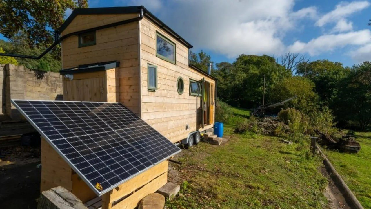
The rough-in for solar is mostly about leaving room for the second phase that always seems to arrive. Even if the first phase is a minimal system, run the DC cables from the planned future array location back to the charge controller position, fit a DC isolator, and over-size the conduit. The cost of spare conduit during the rough-in is trivial; the cost of pulling new cable through a finished wall is not.
Battery placement matters too. Lead-acid batteries need ventilation for hydrogen off-gassing; lithium banks need temperature management. Both need to be physically protected from the elements and from accidental contact, and both need DC-rated overcurrent protection close to the battery terminals.
Anything outdoors must be rated for it. In Australia this means:
Document every circuit as it's run. A simple one-line diagram showing the battery, charge controller, inverter, switchboard, and every final sub-circuit — with cable sizes and breaker ratings — saves hours during fault-finding and is required for insurance and for any future inspection.
Off-grid electrical work sits at the intersection of mains voltage, battery storage, and DC arc-fault risk. That's three sets of hazards in one job, and the consequences of getting it wrong include fire, electrocution, and destroyed equipment. A licensed electrician should:
The installation must comply with AS/NZS 3000, AS/NZS 5033 for solar PV array installations, AS/NZS 4777.2 for inverter installations, AS/NZS 5139 for battery installations, and the applicable state or territory electrical-safety regulations. Relevant examples include the Queensland Electrical Safety Act and requirements administered by Energy Safe Victoria in Victoria.
DIY is acceptable for some DC low-voltage work depending on state rules, but the moment the job touches 230 V AC, RCD selection, MEN earthing, or inverter integration, the licensed professional is no longer optional — they're required.
Can I start with just a battery and inverter and add solar later?
Yes. A 300 W inverter on a 12 V deep-cycle battery, charged from a vehicle or a stand-alone charger, is a viable first phase. Plan the rough-in for the array location, conduit, and charge controller position from day one so the second phase is a component swap, not a re-wire.
A 300 W inverter connected to a 12 V battery draws approximately 25 A continuously before inverter losses. A typical 2 m run would require at least 10 mm² battery cable, with the final size based on the actual route, allowable voltage drop, installation conditions, and AS/NZS requirements. A 48 V starting block is preferable for an inverter-driven cabin because it reduces the DC current and cable sizing burden.
If the battery is charged from a vehicle alternator, use a DC-DC charger sized to the alternator’s output, or charge the battery through an AC mains charger powered by a generator. Never direct-connect a deep-cycle battery to a running vehicle for sustained periods.
Do I need AC at all, or can a cabin run on 12 V DC?
A small cabin can run lighting, a laptop, a woodstove pipe fan, and similar low-draw items directly on DC, without an inverter. Anything with a heating element, a compressor, or a motor above a few hundred watts generally needs AC. The trade-off is operational discipline — DC outlets must be clearly marked and incompatible with AC plugs, because a visitor can fry an appliance in a moment of confusion.
How big should the inverter be?
Match it to the largest simultaneous load plus surge, not the sum of every appliance in the building. Any specific sizing needs the actual load list, which is why the design-before-purchase rule is non-negotiable.
How often should the system be checked?
Annual inspection by a licensed electrician is the baseline — covers RCD trip-time testing, battery state-of-health, cable and connection inspection, and verification that surge protection is still functional.
Is earthing really necessary on an off-grid system with no utility neutral?
Yes. Earthing provides the fault-current path that allows RCDs and breakers to operate, and it protects against surge events including nearby lightning. The inverter and battery bank must be properly bonded to the system earth for any of this to function.
In a stand-alone inverter installation, the MEN link is installed at the inverter AC output as the single neutral-to-earth bond, in accordance with AS/NZS 4777.2 and the inverter manufacturer’s instructions. The battery negative remains isolated and floating in a typical floating DC system unless the battery or inverter manufacturer specifically requires it to be bonded.
What standard governs the install in Australia?
AS/NZS 3000 (the Wiring Rules) is the baseline. The applicable requirements also include AS/NZS 5033 for PV arrays, AS/NZS 4777.2 for inverter installations, and AS/NZS 5139 for battery systems, together with the relevant state or territory electrical-safety regulations. Manufacturer instructions also apply to the selected equipment.
Worth a watch: Roughing In Electrical Boxes In Our DIY Cabin · Poots Pastures